Author Topic: Wiredinput Installation Diagrams" RapidFire Dual Triggers Old/New Board Style"  (Read 65532 times)

Offline KingMike_OS

  • Shop Owner - Products & Support
  • Acidmods Alumni
  • Acid Modder
  • *
  • Posts: 929
  • Post quality +14/-0
  • Gender: Male
  • R&D
    • Modding Shop At the end of the Universe
Parts Needed :

30 awg Kynar Wire
2: Solder, soldering iron and paste
3: 9/64 drill bit "Home depot"
4: Hot Glue Gun and Glue "Home Depot"
5: 2 Tact Switches Button Height 7mm
6: Torx #9 Security Bit
7: Wire strippers "Home Depot"
8: Drill "Home Depot"

Parts Order from the website that installing should be One Of the Fallowing :

PIC 12F683  Old or New Style Controller Preprogram Dual Rapid Fire Triggers Chip Only Or
PIC 12F683   Kit PreWire and Switches Included Old or New Style Controller Preprogram Dual Rapid Fire Triggers

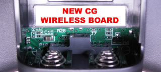
Now Need to Open Your Controller and see What Type of board you have Old or New Style
or you can tell from the back by removing the battary Pack. But Still Need to open it using
the Torx #9 Security Bit or the cheap way by breaking the middle pins and opening it that way
you can google that i'm not going to show you how. Why We Need to know what type of
controller model we have so we can install the Right Chip Or it won't work Right.
Now if you have a Wire Controller You out of luck i don't have one and i never tested.
But I'm Sure that should work But may need to put a 100k resistor on the Power Pin 1 and
that should do the Trick. Everything else should be the same.

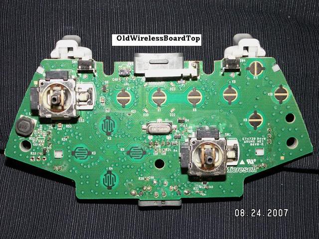
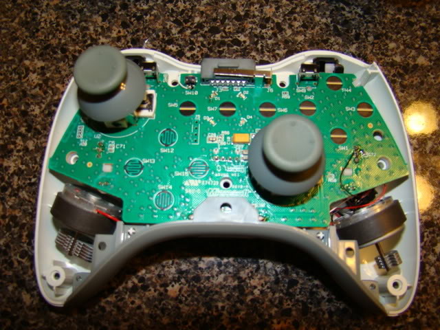
Here Images of both type of controller old and new :


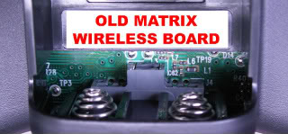
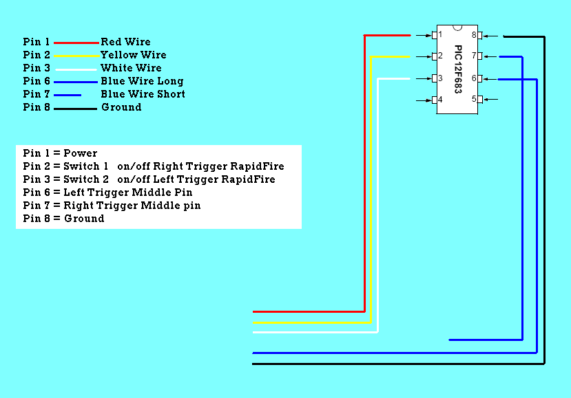
Now that we know what type of board we have here the Digrams for The Colors on a PreWire chips and pin layout
People who just have a chip can wire yours the same way, And PreWires Less work for you Thanks to Me :

Please Check and make Sure The Wiring Match the Digrams [On PreWire Chips] So we Don't Have Any Problem Later
Just In Case I May Wire Diff Color To Diff Pin I'm only Human.  :yess:


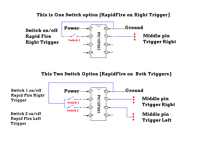
You have 3 option here have to chose what you want to install

1. Rapid Fire On Right Trigger Only " Less Work  Only one hole and one switch"
2. Rapid Fire On Both Trigger  " Lot of work since have to install 2 switches and Glue Them"
3. Rapid Fire Sleeper Setup   " Easy No holes Very Clean No switch Needed"


I will show you all 3 ways installation and digrams Example :


Due to Problem With some of the recharge Pack We are installing all the chip in power saver option
Sleeper & With Switch.
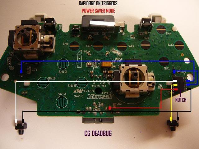
Two Switch New Board Only Power Saver "Save Battery" :
This way the chip is only ON when the controller is ON & OFF to save power when the controller is OFF


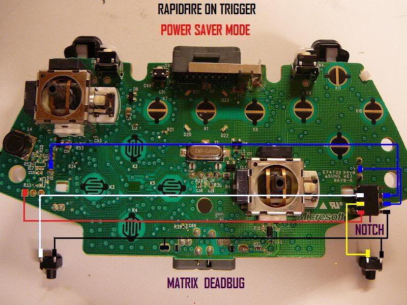
Two Switch Old Board Only Power Saver "Save Battery" Thx GameRoms for Diagrams  :
This way the chip is only ON when the controller is ON & OFF to save power when the controller is OFF


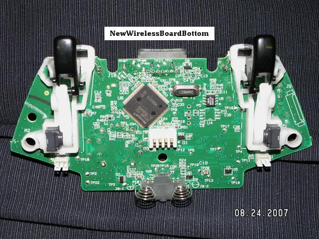
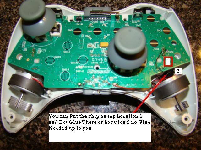
Now Alot of people ask where should i put my chip will here are the 2 place i think is the best


Now Here the Fun Part So far Easy .. Installing your One Switch Or 2 switch

• For both the left and right buttons there is a small oval behind the support for the rumble motors that is leftover from the injection molding process. It is highlighted here in red [Image #2]. I put my holes just behind this and about 1/8th inch lower than the top of the oval. Placement of these buttons are really up to you. For the best fit and location you may want to hold a controller and find the natural resting place of your middle fingers. Once you find your location drill the holes with your 9/64th drill bit.
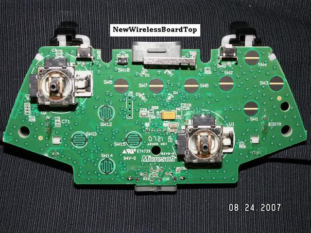
• Next take both of your buttons and we are going to remove one pair of legs because we only need one pair. Use the image so you know which legs to remove. [Image #1]• One at a time put the buttons in there holes and use hot glue to secure them in place. Do not attempt to use super glue or other adhesives as it will soak into the button mechanism and cause it to stop working. [Image #3]


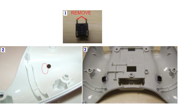
For Wiring please Fallow The Digrams Above [One Switch Or Two Switch]  Remmeber the ground is Comon on the switch you can use pin 8 to grab the ground there or use where i mark next to the Mic Area i don't care pick one.

Remmber You don't have to use Tact Switches Button Height 7mm you can always Use Red Button SPST Push button Switch or Black one Like the Video Below.


<object width="425" height="344"><param name="movie" value="http://www.youtube.com/v/ntPMRurJEbE&hl=en&fs=1"></param><param name="allowFullScreen" value="true"></param><embed src="http://www.youtube.com/v/ntPMRurJEbE&hl=en&fs=1" type="application/x-shockwave-flash" allowfullscreen="true" width="425" height="344"></embed></object>


Now For those of you who want to do Sleeper Setup like Video Below and Don't want any Switches its Clean and much faster.


<object width="425" height="344"><param name="movie" value="http://www.youtube.com/v/fFDEFt2AQ9Q&hl=en&fs=1"></param><param name="allowFullScreen" value="true"></param><embed src="http://www.youtube.com/v/fFDEFt2AQ9Q&hl=en&fs=1" type="application/x-shockwave-flash" allowfullscreen="true" width="425" height="344"></embed></object><object width="425" height="344"><param name="movie" value="http://www.youtube.com/v/HU6-Ls8OSts&hl=en&fs=1"></param><param name="allowFullScreen" value="true"></param><embed src="http://www.youtube.com/v/HU6-Ls8OSts&hl=en&fs=1" type="application/x-shockwave-flash" allowfullscreen="true" width="425" height="344"></embed></object>


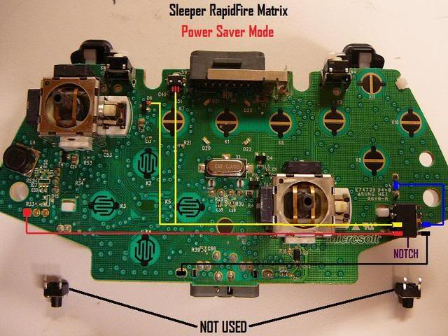
Here The Digram Sleeper "Old Style Controller Only" Power Saver :
Please Use Only One Of the 2 Points on the Yellow Wire. Pick one They Both the same


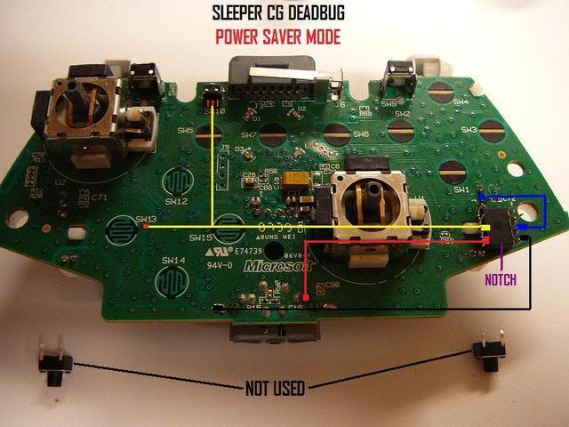
Here The Digram Sleeper "New Style Controller Only" Power Saver :
Please Use Only One Of the 2 Points on the Yellow Wire. Pick one They Both the same


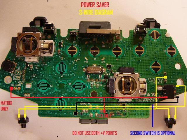
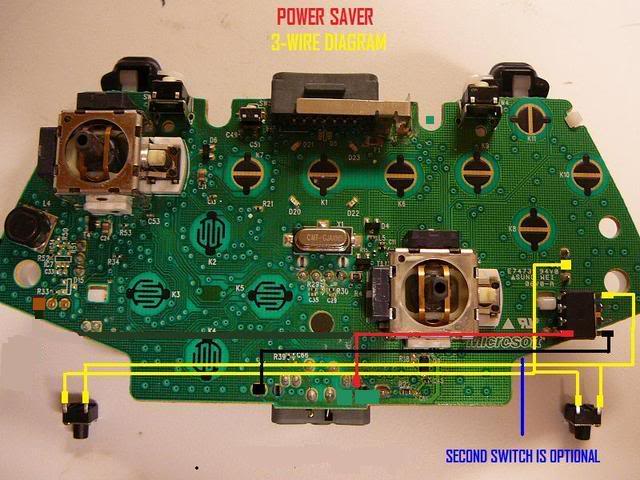
Here The Digram for 3 Wire Kit "New & Old Style Controllers" Power Saver :

Please use the CG Power ON both Model Old And New As On some Old Controller the power Saver
Option Dosent turn the chip On.


Test Time and If Fallow Direction You Should be a Happy Camper  :victory:

Put your Controller Back Together and Please Play Fair " Yeah Right"

KingMike Over & Out  :#1:
« Last Edit: June 27, 2010, 01:59:33 PM by laxboy »

Offline IDontGetHowtoWire

  • ½ Pint
  • *
  • Posts: 37
  • Post quality +0/-0


So the diagram of the chip in that picture is in the dead bug postition?

Offline gameroms

  • Granny Spanker
  • *
  • Posts: 376
  • Post quality +3/-0
the chip must be in dead bug position, in order to mount and close controller.

Offline Nemesis

  • Millennium Poster
  • *
  • Posts: 1186
  • Post quality +0/-0
  • Gender: Male
So the diagram of the chip in that picture is in the dead bug postition?

no it isnt, when its in the dead bug position pin 1 would be on the top right.

Offline KingMike_OS

  • Shop Owner - Products & Support
  • Acidmods Alumni
  • Acid Modder
  • *
  • Posts: 929
  • Post quality +14/-0
  • Gender: Male
  • R&D
    • Modding Shop At the end of the Universe
Quote
the chip must be in dead bug position, in order to mount and close controller.

No you can have it both way .. i cut my chip legs off so it won't run a way..   :rofl:

you can still close it both way .. Just have to be that good.  hehe

« Last Edit: August 01, 2008, 06:48:20 PM by KingMike_OS »

Offline ndrew2505

  • Acid Modder
  • *
  • Posts: 567
  • Post quality +0/-0
  • Gender: Male
whats the link to the kits anyway? i went to wiredinput but everytime i click on the modding shop link it says page can not be found.

Offline KingMike_OS

  • Shop Owner - Products & Support
  • Acidmods Alumni
  • Acid Modder
  • *
  • Posts: 929
  • Post quality +14/-0
  • Gender: Male
  • R&D
    • Modding Shop At the end of the Universe

Offline firestorm2588

  • Guppy
  • *
  • Posts: 5
  • Post quality +0/-0
okokok so im doing the spitfire mod and found the old board style on here is the board i have and the spitfire tutorial has the new board style....does anyone have the pinouts for the old board style???

Offline IDontGetHowtoWire

  • ½ Pint
  • *
  • Posts: 37
  • Post quality +0/-0
no it isnt, when its in the dead bug position pin 1 would be on the top right.

So when, I stand up the chip on the legs and the notch is at the top then, pin 1 is at the top left??

Offline KingMike_OS

  • Shop Owner - Products & Support
  • Acidmods Alumni
  • Acid Modder
  • *
  • Posts: 929
  • Post quality +14/-0
  • Gender: Male
  • R&D
    • Modding Shop At the end of the Universe
Quote
So when, I stand up the chip on the legs and the notch is at the top then, pin 1 is at the top left??
I don't get what is so hard there is large picture of the chip with the number next to each pin .

i can't make it any more simpler.

Offline gameroms

  • Granny Spanker
  • *
  • Posts: 376
  • Post quality +3/-0
look at 10th and 11th pic down in tut.

if that dont help, then there is no help..

Arsic

  • Guest
Re:
« Reply #11 on: August 02, 2008, 06:43:20 PM »
Cool.
« Last Edit: August 11, 2009, 08:58:20 AM by Arsic »

Offline SpartanXx666xX

  • Chief squatting Hard
  • *
  • Posts: 19
  • Post quality +0/-0
so correct if im wrong, but if i am doing the sleeper rapid fire --- i can either choose the power saver method or the normal method...

if i pick the power saver method (i dont know why anyone wouldnt cause its saving power) I am pretty much using the lower pins instead of the top ones??

so the lower pins use less power??

thx :victory:


Offline Bullet Pulse

  • ♪♪♪ Tone deff ♪♪♪
  • *
  • Posts: 55
  • Post quality +0/-0
Do any of the instructions here change if you are using the updated chips?

Offline KingMike_OS

  • Shop Owner - Products & Support
  • Acidmods Alumni
  • Acid Modder
  • *
  • Posts: 929
  • Post quality +14/-0
  • Gender: Male
  • R&D
    • Modding Shop At the end of the Universe
no same installation

illusionistpro

  • Guest
Read through this and that other thread and finally had to register to say damn good job KingMike.  Hopefully the ebay noobs will take 5 min to learn that this is really a 10 min mod, but then again a fool and his money...

Also im putting in my order for a pair of chips.  I was wondering, Can i do a semi-sleeper mod and throw in a clicky switch between the ground?  That way in case i do want to turn it off i can, but still use triggers when i want to?
« Last Edit: August 07, 2008, 05:39:53 PM by illusionistpro »

Offline rulemob

  • Chief squatting Hard
  • *
  • Posts: 18
  • Post quality +0/-0
Can the 3 wire hook up or any way to hook up where you use the added toggle for your rapid fire and not the right trigger? I like the last stand perk so if im running with a m4 and go down i just use the added switch for rapid fire?

Offline JBDizzle

  • Guppy
  • *
  • Posts: 1
  • Post quality +0/-0
I just finished doing the sleeper mod for the old style but it didn't work when I pressed the sleeper button. Did I wire it right?


Offline rulemob

  • Chief squatting Hard
  • *
  • Posts: 18
  • Post quality +0/-0
looks good make sure that your battery is above 2 volts or it wont work. check continuity if you have an ohm meter also your have to push the sync button to turn on right trigger rapid fire and push again to turn off.

Offline jettin33

  • Guppy
  • *
  • Posts: 1
  • Post quality +0/-0
Hi guys,

Is there a way to wire the sleeper setup for LT & RT? From the pictures it looks like the sleeper mode is only wired for RT (pin 2). Can I jumper pins 2 & 3 (soldering pins 6 & 7 accordingly) to get dual rapidfire for Halo 3? My chips are on thier way so haven't had a chance to test.


Thanks in advance.

Offline KingMike_OS

  • Shop Owner - Products & Support
  • Acidmods Alumni
  • Acid Modder
  • *
  • Posts: 929
  • Post quality +14/-0
  • Gender: Male
  • R&D
    • Modding Shop At the end of the Universe
working on something like that but  if you wire both trigger switches to the sync than both are on and both are off you don't have controll on each one. so when playing COD4 you have rapid on your aim as well.

Offline jhyphinwill

  • Chief squatting Hard
  • *
  • Posts: 27
  • Post quality +0/-0
  • Gender: Male
is it possible to wire a led to indicate when rapid fire is on both tiggers? I can get it working on both idividually using pins 8 and 7, or 8 and 6. I only want to install one led to show that rapid is on either trigger.

Offline Blazinkaos

  • Technology Revolution
  • Art & Theme Team
  • E = MC² Mad Scientist
  • *
  • Posts: 2259
  • Post quality +12/-0
  • Gender: Male
  • Time Passes Will You
    • ROOKIE BUILDERS DISCORD
Hey i like that idea. I it has to possible cuz if you place it where you have the sleep and once u turn the sleep off stops the current therefor the LED will also go off.

*Thanks Modders/Friends:Ghost_Death, gr8npwrfl, Blizzrad, Kenshinffx.
*Thanks 802Chives for the Art position!

Offline Jester2893

  • Guppy
  • *
  • Posts: 3
  • Post quality +0/-0
I am using this image as a guide:


Here  is what mine looks like.


I thought I did everything perfect, but I go to try it and nothing happens? The buttons don't make it "rapid fire" you press the buttons and nothing happens.


The only thing I think I could have done wrong was the wiring to the buttons but I reversed the wiring and it still doesn't work.

Offline Blazinkaos

  • Technology Revolution
  • Art & Theme Team
  • E = MC² Mad Scientist
  • *
  • Posts: 2259
  • Post quality +12/-0
  • Gender: Male
  • Time Passes Will You
    • ROOKIE BUILDERS DISCORD
Nice Jester2893 the pics are good and its good nice job...

*Thanks Modders/Friends:Ghost_Death, gr8npwrfl, Blizzrad, Kenshinffx.
*Thanks 802Chives for the Art position!

Offline KingMike_OS

  • Shop Owner - Products & Support
  • Acidmods Alumni
  • Acid Modder
  • *
  • Posts: 929
  • Post quality +14/-0
  • Gender: Male
  • R&D
    • Modding Shop At the end of the Universe
Jester2893 Problem was fix he forgot the Ground. 
He email me and got it working.  :tup:

Offline Jester2893

  • Guppy
  • *
  • Posts: 3
  • Post quality +0/-0
Yup I was a little scared about the soldering but the kit made it so easy because the wires were soldered to the chip already. I also like the fact that the buttons dont do the rapid fire, it just turns it on and off. I have used others where the buttons is the rapid fire.

Very easy install. Thanks a lot.

Offline Hachetman13

  • Guppy
  • *
  • Posts: 1
  • Post quality +0/-0
Awsome mod bought the kit took me 20 min to install worked like a charm.
Take king mikes advice and check the wiring on the chip because my black and blue wires were switched I caught it and it was no problem

Offline quickfire84

  • Guppy
  • *
  • Posts: 1
  • Post quality +0/-0
 :#1:  Just got the rapid fire, w/ LED  work great, awesome mod by kingmike ***** a must!!! g3 is way better lol!!!

Offline FrankieB4

  • Chief squatting Hard
  • *
  • Posts: 10
  • Post quality +0/-0
How do you wire up the black wire for the old style  controller double button mod? There is like another wire intersecting it and its confusing? Any clear wired shots of this? Help is aprecciated


SMF spam blocked by CleanTalk
SimplePortal 2.3.5 © 2008-2012, SimplePortal