|
General ShoutBox
Pages: 1 2 [3] 4 5 ... 10
21
« Last post by RDC on April 09, 2024, 06:26:56 AM »
Top side of the board. 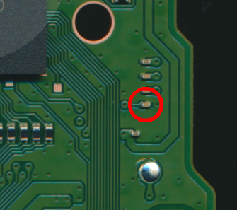
22
« Last post by Darkelf on April 09, 2024, 05:23:37 AM »
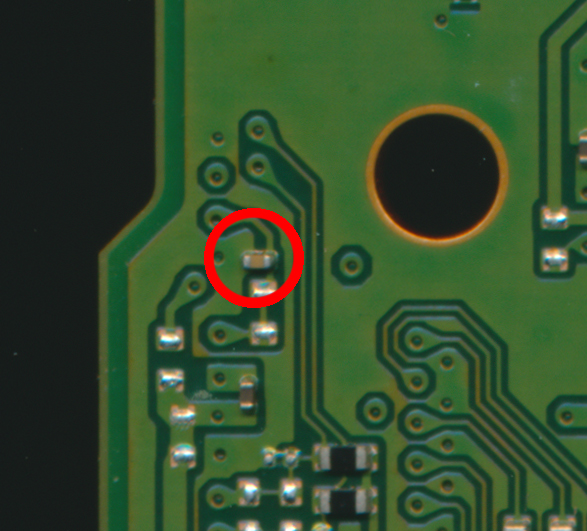
Hello, I have a similar problem. r1 remains pressed all the time. can you help me? (bord BDM020) @ viewrush - If you mean the R2 is always pressed, then try removing this Capacitor first (bottom side of board) and retest.
23
« Last post by RDC on April 08, 2024, 05:45:00 PM »
Don't think I've run across that before. Typically the top board having an issue with L1 or a broken trace will cause that exact issue, but for the bottom board to cause it, it would have to be a bad trace, via, solder connection at the MCU or the MCU itself.
See if the FW will update over USB and if that does anything. I'd suspect not, and then I'd look at the bottom board trace from J5p11 to U1p83 to see if it was open. That's like the 'Power OK' signal from the MCU that keeps the top board powered up so the bottom board will work. If that signal isn't there, you only get power when the Guide button is held down. An issue with D26, Q8 or Q9 and really anything in that circuit there will also cause that issue, but again those are all top board problems and just that Power OK line is all I can think of right now, well that or a bad MCU, that would cause that issue if everything on the top board is good.
24
« Last post by rubs on April 08, 2024, 04:14:02 PM »
Hi guys. I have a controller working fine on USB but it doesn't turn on using batteries (it just flashes 1 time). The top power board is working just fine, I've tested it using another bottom MCU board and everything went ok (using both USB and batteries).
Any suggestion?
25
« Last post by xS7EzRippin on March 30, 2024, 08:41:57 PM »
Yeah, i'm 100% sure it's related to SOC board, done a few readings and the bottom antenna port shorts between the centre pin and the outer side where as the top one (no short but when antenna is connected to this one, the controller will NOT power on, but powers on when the bottom antenna is connected, strange)
26
« Last post by Greendaycolt on March 29, 2024, 01:10:52 PM »
Sorry for late reply - I think the website here was down for a few days. Firmware update fixed the problem. Thanks again, RDC!
27
« Last post by TimeToRelax on March 29, 2024, 12:39:49 PM »
Hello First of all, thank you for making a schematic for various controllers. It made my life so much easier with troubleshooting and repair. I've replaced a lot of analog sticks in Xbox controllers, and I have used two potentiometers for calibration so far and had great success with them. After Microsoft introduced software calibration with a new firmware update, I gave it a shot on my test controller, but it seems that something is wrong with the calibration tool. I did the calibration of two new sticks, and after doing full circles a few times in the tester, my left stick was pushed to the max left and the right one to the down. After disconnecting the USB cable and plugging it back in, sticks are back in the centre but after doing full circles a few times it does the same thing. Here is a test video that I recorded from a gamepad tester https://www.youtube.com/watch?v=ivx0zVsRNtg. Has anybody encountered the same issue or have any thoughts about this?
28
« Last post by Manavie on March 28, 2024, 09:54:28 PM »
I see,
I'll look into the IOVDD pins some more. To clarify writing a 1 to the VOLTAGE_SELECT register would make it use1.8v signal levels, which would fix the issue of sending 3.3v to the DS5 and frying it. The OLED screen (SSD1306) using says that Vdd for IC logic can be from 1.65V to 3.3V, and the Vcc for panel driving should be from 7V to 15V, but I believe that is regulated on the OLED screen module itself, so I think the OLED screen could still work?
Another thing is that, when I just put a voltage divider down to 1.8v to the buttons, they seem to work fine on the OLED? Although this requires a divider for every button lol. I'm not sure if it's because I'm not checking for a "high" input for the logic on my screen, I'm rlly just drawing a bunch of circles as it's default state and then filling them in if the button is set to LOW.
Looking online, it seems there could be some trouble trying to supply with 1.8v due to how the board is*, and that it would also mess up USB functionality according to the DS so I'd still need to give that a 3.3v supply, and I'm not too sure how to supply it to just that one pin. One suggestion that forum post recommends is to use level shifters, could that work? It'd keep the inputs to the DS5 at a 1.8v when not pressed but still 3.3v when going to the board.
*From raspberry pi forums
"Looking at the Raspberry Pi Pico schematics I see that it is possible to tie down 3V3_EN and drive an external, lower voltage on 3V3. unfortunately, according to the schematics, 3V3 is shorted to USB_VDD, that must be driven with 3.3v nominal.
Another option would be to disconnect IOVDD from the 3V3 signal, however, the RP2040 datasheet indicates that all the IOVDD pins must share the same voltage."
29
« Last post by RDC on March 28, 2024, 08:32:40 PM »
The 4 Inputs that make the D-pad/Stick, the ones that will only go to the MC board, do need the PU enabled so they don't 'float' and do any weirdo stuff. Then the 4 that will be going to the DS5 D-pad spots need to be made Inputs when not used, and changed to Outputs and driven Lo when used.
That RP4020 chip needs to be looked into more, as it seems to have IOVDD pins. Unless they tied those to 3.3v on the board, you could run 1.8v to them and not really worry about shooting 3.3v into the 1.8v logic of the controller. That might wreck the OLED, depending on it's IO voltage requirements. Just a quick look at the DS, it looks like having the IO running at 3.3v means it takes 2v to be considered a logic Hi, so connected up to the DS5 that way, the thing will never be able to tell the buttons are not pressed and either 'think' they are pressed all the time or just act all goofy since that 1.8v is close to the 2v requirement.
30
« Last post by crozac on March 28, 2024, 06:16:14 PM »
I have changed that component from a donor board and now it works correctly
Same issue with my controller, it does not work when antenna cable is connected tried to remove all components connected to ground (close to antenna and usb connector) on bottom board but still it does not work what did you replaced at the end to make it work again?
Pages: 1 2 [3] 4 5 ... 10
|

 Recent Posts
