Author Topic: L0rdNiC0s tutorial for the Sound Reactive LED Mod for the Slim  (Read 145294 times)

Offline l0rdnic0

  • 2%
  • Acidmods Alumni
  • E = MC² Mad Scientist
  • *
  • Posts: 1836
  • Post quality +8/-0
  • Gender: Male
  • TeamCYBER

L0rdNiC0s tutorial for the Sound Reactive LED Mod for the Slim
« on: October 27, 2007, 10:45:50 AM »
Well all here it is, I hope you like it. I used other peoples tutorials and I gave credit, however if the names I used are wrong please let me know and I’ll fix it.   :#1:


L0rdNiC0s Sound Reactive LED Mod for the Slim

I would like to point out two things. First Both AcidMods and the author of this document will not and can not be held responsible for any negative results that you may have by performing the actions listed here. In essence Do This At Your Own Risk. Also since you need to open up the slim, you can say goodbye to your warranty!

READ THE FULL DOCUMENT BEFORE YOU START!


Supplies needed for the Sound Reactive LED Mod
30-gauge Kynar wire (best to have different colors)
2x 0603 LED’s
1x 191k-ohm Resistor
1x 30k-ohn Resistor
1x LM386 Audio Amplifier IC
Hot glue gun (optional)
Soldering Iron (nothing more then 15 Watt)
Solder (.015 size works best)
Flux
Drill
3/16 bit
Advanced soldering and PSP disassembly
Access to the Following Tutorials
   PSP Sound Mod by Jrf
   PSP Trigger Mod by Chaos
   PSP Slim & Lite Disassembly Tutorial by T3KN1K4L

What you should do before you start! Copy an MP3 file to the MUSIC folder on your Memory Stick. This will help you test before you have to put your PSP together.

Let’s start by building the sound chip.
Note: Make sure that you use flux and Tin (on/for) all of your wires and connections.

Using Jrf's tutorial build the Sound Mod. You will need to complete ONLY the following steps before we can install.
a.   Cut the legs off the Amp as shown on Jrf’s instructions.
b.   Connect the resistors and Wire that will be run to the speakers
c.   Connect a wire to the 5Volt + Pin
d.   Connect a wire to the Ground –  Pin
e.   Connect a wire to the LED Anode + Pin.
f.   Cut the non used legs off of the LM386
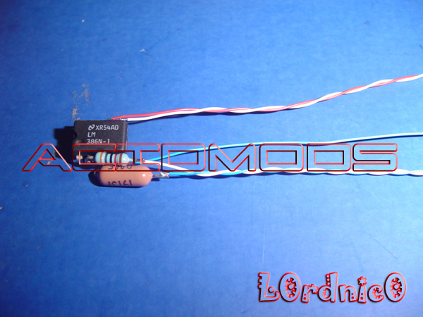
This is what mine looks like. Take note on how I mounted the resistors, I did it this way cause my resistors are on the big side and I wanted this to fit under the heat shield.

Now that you have that stuff built, let’s take the PSP apart. Refer to T3KN1K4L’s PSP Slim & Lite Disassembly Tutorial.
NOTE: you will not be using all the steps in that document. Stop before removing the Mother Board and return to this document (see WiFi Switch).

In the first step you will need to remove the security sticker. I have had much success with removing this sticker without disturbing the security measures (VOID). Take care when removing it, if you peel it to fast or the wrong angle you will separate the martial. If you do it right you can store the sticker (sticky side up) somewhere safe, incase you blow something up….   ;-)

WiFi Switch.
Once you have removed all the cables and the screws that hold the Mother Board in place you’re ready to take it out.
 

MAKE sure you lift from the lower left! Once you can pop up the MB (Mother Board) lift it and pull down as the USB port needs to come out from under the plastic at the top. Also note there is a heat shield under the MB, it’s good to study how this was placed so you can put it back together later (sorry forgot to take this picture).

 
After you have fully extracted the MB flip it over and arrange it so that the USB port is facing away from you and the Memory Stick slot is on the right hand side.

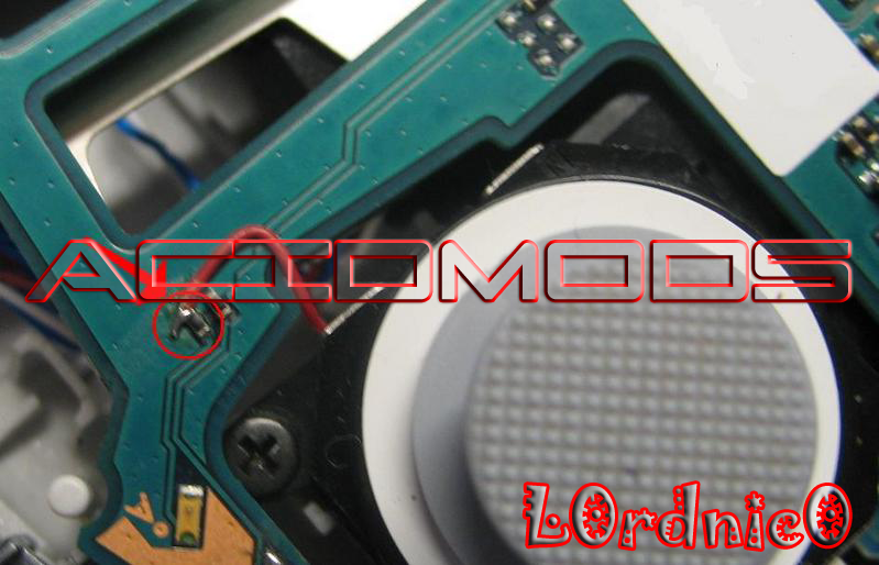
Now you want to focus above the MS (Memory Stick) where you will see the WiFi switch.

The WiFi switch has three leads. I will list them from Left to Right.

Anode +, Cathode -- and Dead

When the switch is on the WiFi mode the Circuit is complete, but when you turn it off the Ground and the Dead pin are connected!! So let’s make it so we can use the switch to Enable/Disable our mod and still use the WiFi

To do this lets grab some Kynar wire and connect the Anode and Cathode pins. It’s best to use flux and tin on both the piece of wire as well as the legs of the switch. This will help you solder the wire nice and clean.

Note: To make this easier I bent a piece of wire into a U shape and bent the ends to away from the center of the U like the Greek Omega Symbol . Since there is not a lot of room in here I was able to hold the wire with clamps and still solder it clean.

Next let’s take another piece of Kynar wire and solder it to the Dead pin (this will serve as our Ground point for the LED’s and the Sound Mod). I recommend using a little more wire then needed to make sure you have enough.


When you’re done it should look like this.
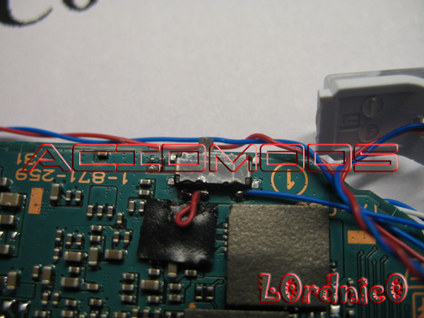

Installing the Sound Mod.

Now take your Amp (Sound Mod) and wire up the Anode + lead.
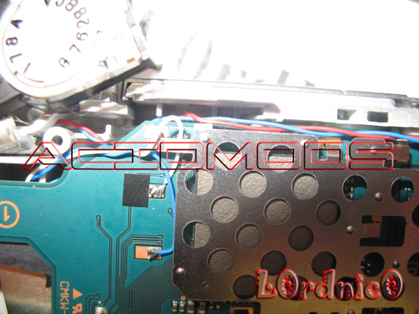
To do this place tape around your Amp and ensure that there is no exposed joints or other metal and place it on the top of the MS cage like so.

Wrap your 5V Wire around the bottom center of the MS where it has a notch as shown here and solder it to the top of the left most resistor.

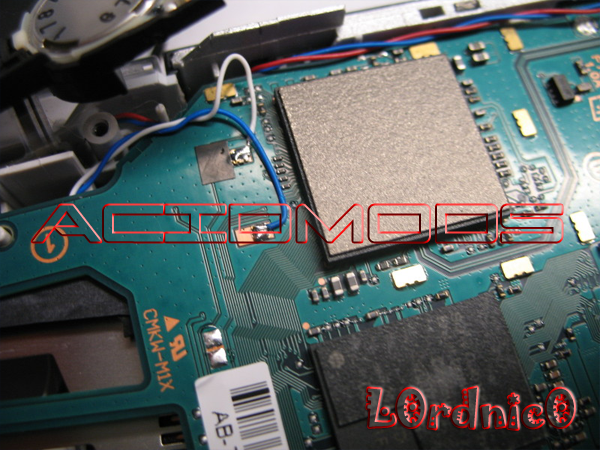
  Now take the two wires that come off the resistors of your Amp and bring them to the top of the MB.  They will be soldered to the contact points of the speaker. Remember that the 191Kohm is positive (that’s the bottom contact point – my Blue wire).  Leave some extra cable here and make sure the wires are run something like mine. If they’re not run this way they will interfere with the directional pad and speaker (your case will not close right).

Building the LED’s.

At this point you will be preparing the LED Shoulder Mod. Please Refer to Chaos’ PSP Trigger Mod for details.
Note: Remember that Chaos’ Tutorial was developed for the Fat PSP. I just used it as a point of reference and the actual trigger drilling process.

To wire the LED’s I found it easiest to do it this way, you may have a different way but that’s taster choice.

1.   Take two pieces of DIFFERENT color Kynar wire and cut at an equal length. Like 8” to 10” inches.
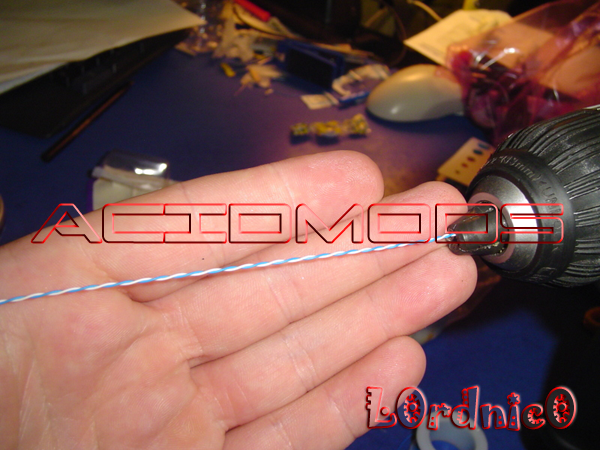
2.     Put them together and place them in the drill (where the bit goes).  Hold the other end of the wires while powering the drill (slowly). This will spin the wires together and add more stability (it also looks cleaner). If you don’t have different color wire, skip this step and step three.
3.   Clip off the end of the wires that were in the drill as the shielding may be damaged.
4.   Line up your SMD and cut one of the wires so when you solder it, it lays flat and then strip a 1/16 inch or less off the end of the other wire,.
5.   Tin the wires and the SMD.
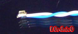
6.   Solder the wires to the LED (Remember which wire goes to the Anode and which to the Cathode).
7.   Your final product should look like this
8.   Repeat steps 1- 6 for as many LED’s as you’re going to use.

Because the triggers have a white plastic coating on them different then the PSP first you will need to drill into the triggers as outlined in Chaos’ LED document as shown here.
Note:  Make sure you drill using the correct angle. I have a vice, if you have access to one use it!

“As you can see, the place I drilled the holes is on the bottom of the button, at the bend, as it is marked here.”
”Use a 3/16” drill bit for the right size.
Slide the LED’s into the holes on the shoulder buttons, and dab a drop of hot glue, into the hole, to seal the LED’s in. This also gives it some structural integrity”


Installing the Mother Board.

Just to make things clear. Right now your Amp has its power wire and the input wires soldered. The wire you soldered to the switch, the Cathode – from the Amp and the Anode + for the LEDS is not connected.

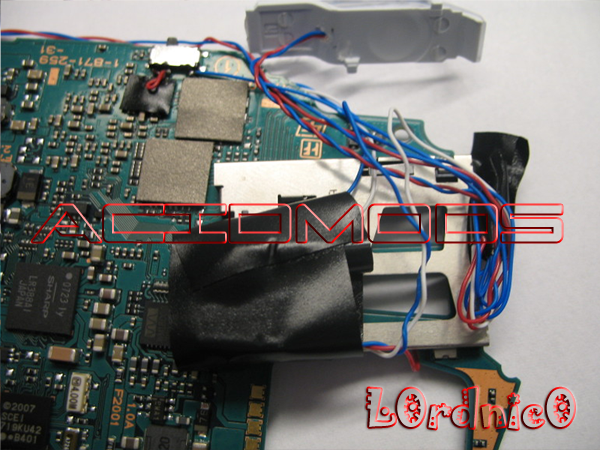
So let’s install the MB but run the non connected wires and the LED wires out from where the MS plugs in. You will want to make sure that the heat shield is in place correctly and that your Amp is under the heat shield when the MB is fully in place.

Now before connecting any wires to the MB (UMD Motor, Power, WiFi antenna etc) put the shoulder buttons in and route the wires as shown below. You will need to bend them so that they don’t interfere when you press the button down.

Left Side Routed. (Note how the trigger wires are routed)
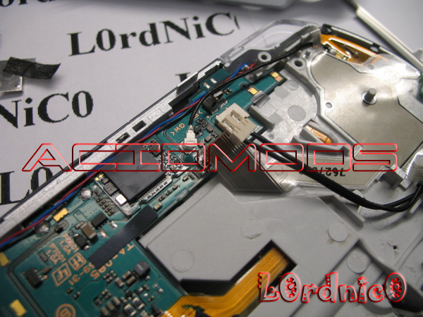
Right Side Routed. (Note how the trigger wires are routed. Blue should be below the post by the red.)


Finish and test.

With all the wires sticking out the Left side of the PSP where the MS goes, take all the Cathode – wires from your LED’s and the Cathode – wire from the switch, cut them so that you don’t have any excess wire and then solder them together.

Next take the Anode + wire from the Amp and then the Anode + wires from your leads and cut them so that there is no excess wire and then solder them.

Put your battery in the PSP and turn the WiFi switch to the off position (this turns the LED’s on). Then turn on the PSP and your LED’s should light up. If they don’t you did something wrong! Check your setup.

If you want to see them blinking but haven’t connected your screen then insert your memory card. Turn on the PSP and using the rubber piece from your /\ [] O X button do the following:

Tap the rubber thing on the right directional pad one time. Then tap the left directional pad three times. Then use the rubber thing to press the /\ button and then the X button. This should start playing a song… OH yeah, turn up your volume for more blinky blink. It helps to have a speaker connected so you can hear the beeps as you navigate the menu.

Clean UP.

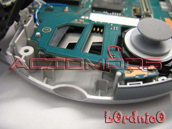
Tape up your exposed wires and stuff them in the opening under the MS slot. Note: try to keep this area clean and neat as the tabs on the MS cover slide into the area where your new wires are. It may take you a few tries but test it out before you put your PSP together so that you’re not disappointed.

Take out your MS if it’s still in the card reader and put your PSP back together and enjoy.


Special thanks to the following!!!
General_Badger
: I wouldn’t have gotten a PSP if I hadn’t messed with yours.
Vivian: Thanks for the use of your camera’s Macro feature.
Simcityltd: Thanks for the watermarks

Check YouTube for an install video (coming soon)  :hifive:
« Last Edit: November 24, 2007, 04:35:46 AM by *FuFa »


L0rdNiC0 Pioneering Mods on the PSP Slim :taunt:
Sound Mod, Button LED Mod, Security Mod, Dual NUB, Mode Select Switch + More

edhel

  • Guest
Re: L0rdNiC0s tutorial for the Sound Reactive LED Mod for the Slim
« Reply #1 on: October 27, 2007, 10:50:18 AM »
brilliant tutorial - thanks so much man  :hifive:

Offline simcityltd

  • Cyberpyrot's Personal Assistant
  • Acidmods Alumni
  • Granny Spanker
  • *
  • Posts: 414
  • Post quality +0/-0
  • Gender: Male

    • AcidMods
Re: L0rdNiC0s tutorial for the Sound Reactive LED Mod for the Slim
« Reply #2 on: October 27, 2007, 10:52:07 AM »
Awesome Tut

When T3K Comes Online, I will get hi to add it into the wiki :D

Offline simcher

  • Chief squatting Hard
  • *
  • Posts: 13
  • Post quality +0/-0
Re: L0rdNiC0s tutorial for the Sound Reactive LED Mod for the Slim
« Reply #3 on: October 27, 2007, 11:42:39 AM »
nice to see the tutorial finally up, but alot of stuff is beyond me... :( i can't seems to see where does the +5v and GND goes... omg... a schematic will be great help here... :D

Edit:
Quote
Wrap your 5V Wire around the bottom center of the MS where it has a notch as shown here and solder it to the top of the left most resistor.

i think you left out this picture? :D

simcityltd: Please edit your first post and not double post. Thanks :)

« Last Edit: October 27, 2007, 12:00:43 PM by simcityltd »

Offline l0rdnic0

  • 2%
  • Acidmods Alumni
  • E = MC² Mad Scientist
  • *
  • Posts: 1836
  • Post quality +8/-0
  • Gender: Male
  • TeamCYBER

Re: L0rdNiC0s tutorial for the Sound Reactive LED Mod for the Slim
« Reply #4 on: October 27, 2007, 12:33:57 PM »
I have the hardest time with that picture... Well Its there now!!!  :boxed:


L0rdNiC0 Pioneering Mods on the PSP Slim :taunt:
Sound Mod, Button LED Mod, Security Mod, Dual NUB, Mode Select Switch + More

Offline PspKicks316

  • Acidmods Alumni
  • Mad Bomber
  • *
  • Posts: 5709
  • Post quality +5/-4
  • Gender: Male
Re: L0rdNiC0s tutorial for the Sound Reactive LED Mod for the Slim
« Reply #5 on: October 27, 2007, 03:37:39 PM »
Very,Very nice tutorial Lordnic0,Awesome man!

Offline l0rdnic0

  • 2%
  • Acidmods Alumni
  • E = MC² Mad Scientist
  • *
  • Posts: 1836
  • Post quality +8/-0
  • Gender: Male
  • TeamCYBER

Re: L0rdNiC0s tutorial for the Sound Reactive LED Mod for the Slim
« Reply #6 on: October 27, 2007, 03:46:15 PM »
Thanks lots, hope it has enough detail and that its easy to follow!!

EDIT: I wanted to know if anyone used this Tut and found it helpfull? :dntknw:
« Last Edit: November 06, 2007, 03:19:51 PM by Nemesis »


L0rdNiC0 Pioneering Mods on the PSP Slim :taunt:
Sound Mod, Button LED Mod, Security Mod, Dual NUB, Mode Select Switch + More

Offline dedafmonteur

  • E = MC² Mad Scientist
  • *
  • Posts: 2049
  • Post quality +4/-0
  • Gender: Male
Re: L0rdNiC0s tutorial for the Sound Reactive LED Mod for the Slim
« Reply #7 on: November 01, 2007, 02:16:53 AM »
VERRY nice.....

sticked! :yess:

Offline l0rdnic0

  • 2%
  • Acidmods Alumni
  • E = MC² Mad Scientist
  • *
  • Posts: 1836
  • Post quality +8/-0
  • Gender: Male
  • TeamCYBER

Re: L0rdNiC0s tutorial for the Sound Reactive LED Mod for the Slim
« Reply #8 on: November 01, 2007, 09:45:30 AM »
Thanks!!!!!! I hope to see this added to the WiKi if people find it usefull..... 

Thanks Again to all you AcidModders!!!!!! :tup:


L0rdNiC0 Pioneering Mods on the PSP Slim :taunt:
Sound Mod, Button LED Mod, Security Mod, Dual NUB, Mode Select Switch + More

Offline bottmint

  • Guppy
  • *
  • Posts: 6
  • Post quality +0/-0
Re: L0rdNiC0s tutorial for the Sound Reactive LED Mod for the Slim
« Reply #9 on: November 07, 2007, 07:32:45 PM »
dude thank you thank you thank you :clap: :clap: this is awesome. i was hoping to mod the slim without extra things on the outside. this is # :#1: once i get this done im going to show it off and tell where i learned to do it  :psp: just 1 question though. Where did you buy all the parts or what store/site did you get it from? im desperate  :beg: thnx in advance

Offline l0rdnic0

  • 2%
  • Acidmods Alumni
  • E = MC² Mad Scientist
  • *
  • Posts: 1836
  • Post quality +8/-0
  • Gender: Male
  • TeamCYBER

Re: L0rdNiC0s tutorial for the Sound Reactive LED Mod for the Slim
« Reply #10 on: November 07, 2007, 07:50:33 PM »
The shack has the LM386 anf the rest of the parts from mouser.com, however you could probably get them from anywhere....

When your done come back and let me know how you made out. I just did my 6th one last night. :tup:


L0rdNiC0 Pioneering Mods on the PSP Slim :taunt:
Sound Mod, Button LED Mod, Security Mod, Dual NUB, Mode Select Switch + More

Offline bottmint

  • Guppy
  • *
  • Posts: 6
  • Post quality +0/-0
Re: L0rdNiC0s tutorial for the Sound Reactive LED Mod for the Slim
« Reply #11 on: November 08, 2007, 05:36:05 AM »
thanx man im going to try to get the money and do it as soon as possible this is an awesome mod :yess: :clap:

Offline cyberpunk

  • ½ Pint
  • *
  • Posts: 34
  • Post quality +0/-0
  • Gender: Male
Re: L0rdNiC0s tutorial for the Sound Reactive LED Mod for the Slim
« Reply #12 on: November 14, 2007, 11:56:21 AM »
Any progress on the video tutorial?  :beg:

Offline l0rdnic0

  • 2%
  • Acidmods Alumni
  • E = MC² Mad Scientist
  • *
  • Posts: 1836
  • Post quality +8/-0
  • Gender: Male
  • TeamCYBER

Re: L0rdNiC0s tutorial for the Sound Reactive LED Mod for the Slim
« Reply #13 on: November 14, 2007, 08:40:49 PM »
Funny you should ask... Tonight I shot some more steps... I don't want to post them untill I have all the steps complete.  I'm almost done  :psp:


L0rdNiC0 Pioneering Mods on the PSP Slim :taunt:
Sound Mod, Button LED Mod, Security Mod, Dual NUB, Mode Select Switch + More

Offline cyberpunk

  • ½ Pint
  • *
  • Posts: 34
  • Post quality +0/-0
  • Gender: Male
Re: L0rdNiC0s tutorial for the Sound Reactive LED Mod for the Slim
« Reply #14 on: November 15, 2007, 06:31:22 AM »
Great!  Can't wait.

Offline bottmint

  • Guppy
  • *
  • Posts: 6
  • Post quality +0/-0
Re: L0rdNiC0s tutorial for the Sound Reactive LED Mod for the Slim
« Reply #15 on: November 23, 2007, 10:50:39 PM »
hey how much money would you need to get all the parts and for all the labor? i just havent been able to get to the ordering and i dont think i want to take a risk of soldering wrong and i know that you can do it good. and if not o well lol EDIT: can you pm me the response? tia
« Last Edit: November 23, 2007, 10:57:42 PM by bottmint »

Offline *FuFa

  • learn2/spell/
  • Millennium Poster
  • *
  • Posts: 1316
  • Post quality +0/-0
  • Gender: Male
  • Spam King Barfday Boy¯\(°_o)/¯ ¯\(°_o)/¯ ¯\(°_o)/¯
Re: L0rdNiC0s tutorial for the Sound Reactive LED Mod for the Slim
« Reply #16 on: November 24, 2007, 04:34:50 AM »
Didn't ever notice your tutorial, sorry, just wanted to tell you that the Sound Mod wasn't done by me, it was done by jrf , my name is only showed because I edited some pictures in the wiki. Great Tut btw.

Have no shame in being kindly and gentle, but if the time comes in the time of your life to kill, kill and have no regret. In the time of your life, live so that, in that wonderous time you shall not add to the misery and sorrow of the world, but shall smile to the infinite delight and mystery of it.

Offline l0rdnic0

  • 2%
  • Acidmods Alumni
  • E = MC² Mad Scientist
  • *
  • Posts: 1836
  • Post quality +8/-0
  • Gender: Male
  • TeamCYBER

Re: L0rdNiC0s tutorial for the Sound Reactive LED Mod for the Slim
« Reply #17 on: November 24, 2007, 05:38:35 PM »
Much luv Fufa!! Thanks for the update. :hifive:


L0rdNiC0 Pioneering Mods on the PSP Slim :taunt:
Sound Mod, Button LED Mod, Security Mod, Dual NUB, Mode Select Switch + More

Offline *FuFa

  • learn2/spell/
  • Millennium Poster
  • *
  • Posts: 1316
  • Post quality +0/-0
  • Gender: Male
  • Spam King Barfday Boy¯\(°_o)/¯ ¯\(°_o)/¯ ¯\(°_o)/¯
Re: L0rdNiC0s tutorial for the Sound Reactive LED Mod for the Slim
« Reply #18 on: November 24, 2007, 05:47:29 PM »
Much luv Fufa!! Thanks for the update. :hifive:

No problem man :)

Have no shame in being kindly and gentle, but if the time comes in the time of your life to kill, kill and have no regret. In the time of your life, live so that, in that wonderous time you shall not add to the misery and sorrow of the world, but shall smile to the infinite delight and mystery of it.

Offline spelman07

  • BANNED
  • Ω Allumnist Ω
  • *
  • Posts: 103
  • Post quality +0/-0
  • Gender: Female
Re: L0rdNiC0s tutorial for the Sound Reactive LED Mod for the Slim
« Reply #19 on: December 08, 2007, 02:33:40 PM »
im doing this mod now where can i buy 1x 191k-ohm Resistor

ive searched everywhere need from uk though :p

Offline Nemesis

  • Millennium Poster
  • *
  • Posts: 1186
  • Post quality +0/-0
  • Gender: Male
Re: L0rdNiC0s tutorial for the Sound Reactive LED Mod for the Slim
« Reply #20 on: December 08, 2007, 02:56:13 PM »
possibly maplins or ebay or local electronic store?
if there is a maplin near you they would definately have some

Offline Nemesis

  • Millennium Poster
  • *
  • Posts: 1186
  • Post quality +0/-0
  • Gender: Male
Re: L0rdNiC0s tutorial for the Sound Reactive LED Mod for the Slim
« Reply #21 on: December 09, 2007, 01:44:51 PM »
really? maplins have a whole load of resistors but maybe not that one.. ill check

Offline l0rdnic0

  • 2%
  • Acidmods Alumni
  • E = MC² Mad Scientist
  • *
  • Posts: 1836
  • Post quality +8/-0
  • Gender: Male
  • TeamCYBER

Re: L0rdNiC0s tutorial for the Sound Reactive LED Mod for the Slim
« Reply #22 on: December 09, 2007, 01:55:06 PM »
for connectiong the + and - at the wifi switch why did u use wire and not just put a blob of solder on there?
I did that incase I wanted to take that off one day. IDK I like having options.  :dntknw:

EDIT:
im doing this mod now where can i buy 1x 191k-ohm Resistor

ive searched everywhere need from uk though :p

I got mine from mouser.com they ship to the UK from what I understand. If you need I can mail some to you (snail mail)

Nemesis: How could you l0rdnic0, double posting tut tut lol, remember no double posting
« Last Edit: December 11, 2007, 09:59:48 AM by Nemesis »


L0rdNiC0 Pioneering Mods on the PSP Slim :taunt:
Sound Mod, Button LED Mod, Security Mod, Dual NUB, Mode Select Switch + More

Offline yudi

  • Guppy
  • *
  • Posts: 1
  • Post quality +0/-0
Re: L0rdNiC0s tutorial for the Sound Reactive LED Mod for the Slim
« Reply #23 on: December 10, 2007, 05:58:42 AM »
SPLENDID MAN... THAT'LL PUT SUMTHIN IN MY MIND!! :#1:

LOOKIN FRWRD FOR MORE FRM U.

Offline l0rdnic0

  • 2%
  • Acidmods Alumni
  • E = MC² Mad Scientist
  • *
  • Posts: 1836
  • Post quality +8/-0
  • Gender: Male
  • TeamCYBER

Re: L0rdNiC0s tutorial for the Sound Reactive LED Mod for the Slim
« Reply #24 on: December 10, 2007, 06:38:54 AM »
Quote
Nemesis: How could l0rdnic0, double posting tut tut lol, remember no double posting

Sorry want thinking very well when I was here yesterday. You know a little  :drunk:
« Last Edit: December 10, 2007, 05:31:28 PM by l0rdnic0 »


L0rdNiC0 Pioneering Mods on the PSP Slim :taunt:
Sound Mod, Button LED Mod, Security Mod, Dual NUB, Mode Select Switch + More

Offline bottmint

  • Guppy
  • *
  • Posts: 6
  • Post quality +0/-0
Re: L0rdNiC0s tutorial for the Sound Reactive LED Mod for the Slim
« Reply #25 on: December 18, 2007, 06:39:25 PM »
 :whoosh: nother question from the guppy lol does the ic sound amp make the speakers louder? i doubt it but i want to make sure and is there anyway to get the leds brighter?

Offline slslasher

  • ♪♪♪ Tone deff ♪♪♪
  • *
  • Posts: 73
  • Post quality +0/-0
Re: L0rdNiC0s tutorial for the Sound Reactive LED Mod for the Slim
« Reply #26 on: December 28, 2007, 05:22:54 AM »
i cant find any 191k ohm resistor??can i use 180k ohm and 11k ohm soldered together??and my ic heat up super fast n super hot??is there anyway to make it cool down?

Offline slslasher

  • ♪♪♪ Tone deff ♪♪♪
  • *
  • Posts: 73
  • Post quality +0/-0
Re: L0rdNiC0s tutorial for the Sound Reactive LED Mod for the Slim
« Reply #27 on: December 28, 2007, 05:29:36 AM »
i think becoz i go use the 33k ohm resistor.i going buy 30k ohm resistor tmr. thxs for letting mi know i can connect in series ^^ I go to a lot of shop todae all nvr sell 191k ohm, they sae is veri rare.

Offline Nemesis

  • Millennium Poster
  • *
  • Posts: 1186
  • Post quality +0/-0
  • Gender: Male
Re: L0rdNiC0s tutorial for the Sound Reactive LED Mod for the Slim
« Reply #28 on: December 28, 2007, 05:40:23 AM »
i think becoz i go use the 33k ohm resistor.i going buy 30k ohm resistor tmr. thxs for letting mi know i can connect in series ^^ I go to a lot of shop todae all nvr sell 191k ohm, they sae is veri rare.

yea i had trouble finding them too but just make sure you are using right resistors even if they are a few ohms over what you need :)

Offline slslasher

  • ♪♪♪ Tone deff ♪♪♪
  • *
  • Posts: 73
  • Post quality +0/-0
Re: L0rdNiC0s tutorial for the Sound Reactive LED Mod for the Slim
« Reply #29 on: December 28, 2007, 05:56:22 AM »
yea i had trouble finding them too but just make sure you are using right resistors even if they are a few ohms over what you need :)
my led burst becoz too much votage go through it and my trigger was burnt.so i juz use insulating tape n tape around the ic chip and it will not heat up so fast if i put in under the heat sink??


SMF spam blocked by CleanTalk
SimplePortal 2.3.5 © 2008-2012, SimplePortal